Date: Mon, 17 Oct 2016 17:22:53 +0200
Dear all,
Thank you all for your answers.
You have cleared up a lot for me.
Franz, being able to read the .vxl files have been something I've been
wondering about, so that is really helpful!
I also found the CORRFACT cards in the output right after I submitted my
mail. I should really get better at looking into the output files. I also
there noticed that the correction factors to the stopping power were
applied having, however, negative values. So providing the CdEdx_rel_min
and CdEdx_rel_max using negative values makes perfect sense.
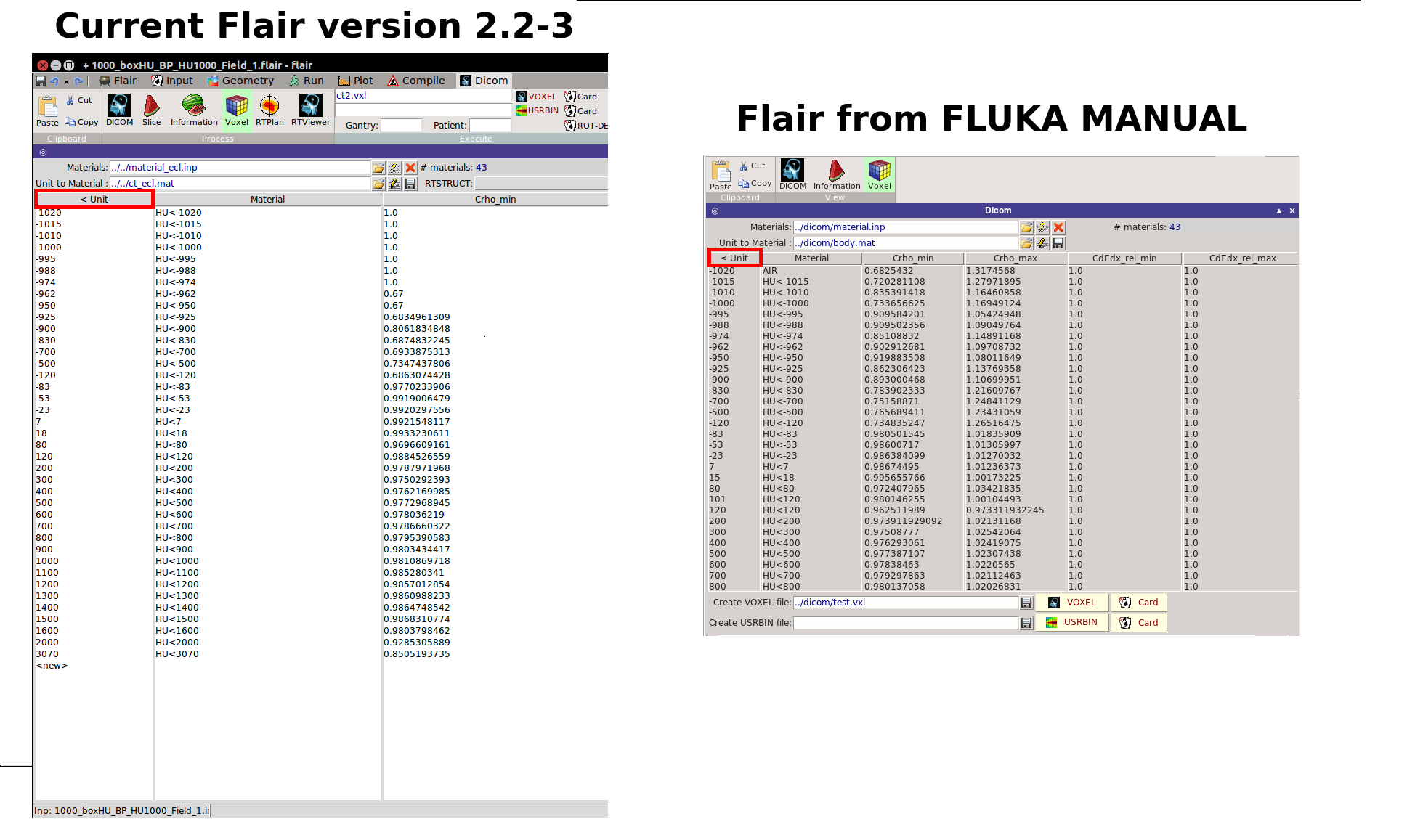
I was actually rather referring to the unit specification on the far left
in the voxel tab and not the materials. If you look at the red boxes
outlined in the attached image, there was previously in Flair (image from
the manual) unit specified using < with a line beneath (<=), and now in the
current versions of Flair, this line has been removed (<). I presume that
this line should still be in Flair considering the HUs are given in less or
equal. Or am I misunderstanding?
Now that we have established that the HU-range is taken as <=, it brings me
to a follow-up question, if you don't mind.
If I extend my previous example:
< Unit Material Crho_min Crho_max
900 HU<900 0.9803 1.0192
1000 HU<1000 0.9810 1.0168
1100 HU<1100 0.9853 1.0144
The HU<1000 material is defined as having a density of 1.5873 g/cm3. So
this density will correspond to HU=950, and should be scaled according to
the correction factors (0.9810 and 1.0168) for material HU<1000.
And the since my HU=1000 is given the material HU<1000, I would then
believe that the correction factor to the density should be 1.0168, i.e. an
up-scaling from the density of 1.5873 g/cm3 to arrive at 1.6140 g/cm3.
However, when I look at the CORRFACT in the output file the following is
given:
***** Next control card ***** CORRFACT -1.000 0.9853 0.000
6.000 0.000 0.000
and
6 VOXEL002 60 HU<1000 OFF 0.00000E+00 9.99852E+04
( 60 HU<1000 OFF )
So the region number 6 (6.000 in the CORRFACT) is my HU=1000 (material
HU<1000) region. And as you can see, the correction factor applied to this
region is 0.9853, equal to the lower correction factor of material HU<1100.
Material HU<1100 have a density of 1.6387 g/cm3 so I will arrive at a final
density of 1.6146 g/cm3 (which is basically the same as the previously
mentioned up-scaling to 1.6146 g/cm3). Even though the final value of the
density will practically be the same for both cases, is it not therefore an
incon
sistency, considering that the materials are given by Hounsfield units
as <=, while apparently the correction factors are given by Hounsfield
units as < ?
Thank you very much again!
---
*Lars Fredrik Fjæra*
On Mon, Oct 17, 2016 at 11:34 AM, Franz Siegfried Englbrecht <
Franz.Englbrecht_at_physik.uni-muenchen.de> wrote:
> Dear Lars, dear FLUKA Users,
>
> I want to adress only the question of 'So where are these CORRFACT cards?'
>
> You can, on a linux machine, adress the ASCII content of the binary .vlx
> file by typing 'strings FILE.vlx'. There you will find the automatically
> generated cards.
>
> Best,
> Franz
>
>
>
> Quoting Lars Fredrik Fjæra <lfj049_at_student.uib.no>:
>
> Dear FLUKA users,
>>
>> I have two problems I want to address.
>>
>> First, is there an error in the Flair Dicom/Voxel tab? The unit range on
>> the far left specifies Hounsfield units "less than" (<), however, when I
>> was using artificial CT-scans, I noticed that Flair applies materials
>> according to units of "less or equal" (<=). As an example, I have the
>> following defined:
>>
>> < Unit          Material          Crho_min          Crho_max
>> 1000           HU<1000        0.9810               1.0168
>> 1100           HU<1100         0.9852               1.0144
>>
>> In my CT scan I have only two Hounsfield units, HU=1000 and HU=-1000.
>> Using
>> the HU=1000 as an example, it should, according to Flair, be assigned the
>> material called HU<1100 considering that 999<HU1000<1100. However, the HU
>> of 1000 gets assigned the material HU<1000. This then means that the unit
>> specification in Flair should be (=<). I have also noticed that this was
>> the case in previous versions in Flair referring to for example the image
>> in the manual. I have also attached images of my voxel/geometry setup to
>> further illustrate the problem. The same also happens for my HU=-1000. It
>> gets assigned the material HU<-1000 specified with the unit <-1000, where
>> it really should be assigned the material HU<-1010.
>>
>> Next problem. I really miss a proper explanation/documentation of the
>> stopping power calibration in the voxel tab. Performing the density
>> calibration (Crho_min and Crho_max) is straight forward and works
>> perfectly. I am however struggling with dE/dx calibration. First off, it
>> is
>> specified that the dE/dx correction are relative corrections. Relative to
>> what? According to the manual, "dE/dx is applied relative to the
>> correction
>> of density (negative WHAT(1) in CORRFACT)". However, I was under the
>> impression that if you perform the calibration in the .vxl file itself,
>> you
>> don't need any separate CORRFACT cards? The manual also states:
>> "CdEdx_rel_min:  relative correction factor on dE/dx for the minimum unit
>> in the range         CdEdx_rel_max:  relative correction factor on dE/dx
>> for the maximum unit in the range". So then I wonder, is the correction
>> applied to the density corrections? I.e. If I have rho = 1, and Crho_max =
>> 1.5 and CdEdx_rel_max = 1.5, the effective density for the stopping power
>> will be 2.25?
>> Further, from the FLUKA course slides about medical application, there is
>> a
>> sentence that states "FLAIR automatically appends the CORRFACT cards
>> calculated taking into account the calibration curves provided by the user
>> at the end of the .vxl file." So where are these CORRFACT cards?
>> And to add to all this, I have been playing around with the  CdEdx_rel_min
>> and  CdEdx_rel_max, just trying to change them to see if I can obtain some
>> difference in the simulated ranges for Bragg peaks. However, I can apply
>> whatever value to CdEdx_rel_min and  CdEdx_rel_max, and still obtain
>> exactly the same curves. I've even tried to obtain an error in my
>> simulations by setting the CdEdx_rel_min and  CdEdx_rel_max beyond the
>> range [2/3,3/2], however the simulation runs fine. I did the same thing
>> for
>> the Crho_min and max, where I successfully obtained an error. So it seems
>> that FLUKA doesn't even take into account my input to CdEdx_rel_min and
>>  CdEdx_rel_max. On the other hand, I am perfectly able to apply
>> corrections
>> using regular CORRFACT cards. Can someone please explain thoroughly how to
>> properly use CdEdx_rel_min and  CdEdx_rel_max?
>>
>> Thank you!
>>
>> ---
>> *Lars Fredrik Fjæra*
>>
>
>
>
>
__________________________________________________________________________
You can manage unsubscription from this mailing list at https://www.fluka.org/fluka.php?id=acc_info
(image/png attachment: Flair_unit_specification.png)