|
|
|
|
Quick launch:
Last version:
News:
--
Fluka Release
|
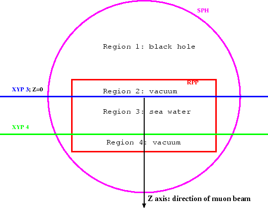
[ 1 ] [ 2 ] [ 3 ] [ 4 ] [ 5 ] [ 6 ] [ 7 ] [ 8 ] [ 9 ] [ 10 ] [ 11 ] [ 12 ] [ 13 ] [ 14 ] [ 15 ] [ back ] Since the main purpose of this example is to describe the technicalities of interfacing the HBOOK routines, we shall not consider a sophisticated geometrical description and we shall limit ourselves to the simple approximation of a single large volume uniformly filled by water having homogeneous properties. This can be easily obtained using a Rectangular Parallelepiped body (RPP) with one edge parallel to the propagation axis (Z). In case variation of material properties (such as the density) as a function of depth must be considered, one should prepare different bodies to be positioned one after the other, so to fill them with different materials. We remind here that all physical regions must be embedded inside an enclosing volume, defined to be a "black hole" material, so to stop the tracking of all escaping particles. We can choose a large sphere (SPH) to describe the external boundary of this enclosing volume. Since muons must be injected just above the water surface and since, by definition, they cannot be injected in a "black body" medium, it can be convenient to define a limited vacuum region just above the water volume. It is convenient to do the same just after the depth at which scoring is performed. All this can be easily implemented by cutting the RPP volume by two planes orthogonal to the Z axis (XYP bodies), respectively at Z = Zmin and Z = Zmax such that Zmax – Zmin = Depth, where Depth is the desired thickness of water. The extreme Z coordinates of the RPP body, Z1 < Zmin and Z2 > Zmax, will be chosen so that Zmin – Z1 and Z2 – Zmax will respectively define the desired vacuum layers above and below the water volume. In summary, the geometrical setup will be the one depicted in Fig. 1.
The bodies can be defined in the geometry data cards (free format with names) according to the following lines: SPH LARGESPH 0.0 0.0 0.0 5000000.0 RPP WORLD -1000000.0 1000000.0 -1000000.0 1000000.0 -100.0 100100.0 XYP SEATOP 0.0 XYP SEABOT 100000.0 END Here Z1 = –100 cm and Z2 = 100100 cm, while Zmin = 0 and Zmax = 100000 cm. The initial and final vacuum layers are therefore 100 cm deep. From these bodies, the following regions (to be assigned a specific material) are defined: * black hole BLACKHOL 5 +LARGESPH -WORLD * vacuum at the beginning VACTOP 5 +WORLD +SEATOP * water layer SEA 5 +WORLD +SEABOT -SEATOP * vacuum at the end VACBOT 5 +WORLD -SEABOT END The black hole will be the 1st region (named BLACKHOL): the space contained within the body LARGESPH (SPH) and outside the body WORLD (RPP). The initial vacuum will be the region #2 (named VACTOP): the space within the body WORLD (RPP) and above the XYP plane named SEATOP. The water volume will be the 3rd region (named SEA): the space within the body WORLD (RPP) and delimited by the two XYP planes (SEATOP and SEABOT). The 4th region (named VACBOT) is at the bottom boundary of the sea-water region SEA (within the body WORLD (RPP) and below the XYP plane named SEABOT) and will be defined as a vacuum region.
Giuseppe Battistoni; INFN, Milano
Last updated: 10th of December, 2008 |


© FLUKA Team 2000–2024