|
|
|
|
Quick launch:
Last version:
News:
--
Fluka Release
|
[ 1 ] [ 2 ] [ 3 ] [ 4 ] [ 5 ] [ 6 ] [ 7 ] [ 8 ] [ 9 ] [ 10 ] [ back ]
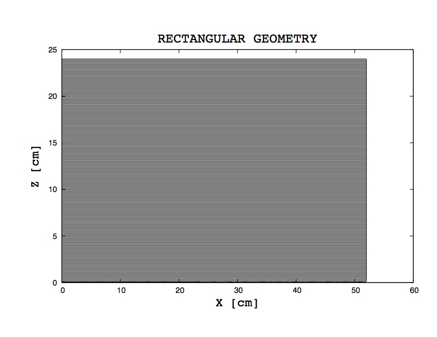
The module geometry was designed trying to profit of the big degree of
symmetry of the calorimeter structure. The first version of this geometry was
realized in rectangular shape [Implementation to FLUKA package was done
by: G. Battistoni, B. Di Micco, A. Ferrari, A. Passeri
and V. Patera ] with the material description given in the previous
section.
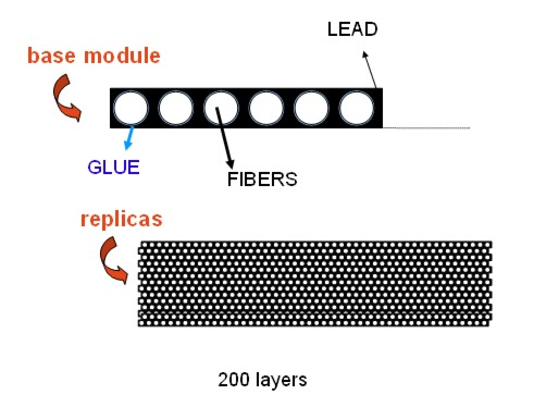
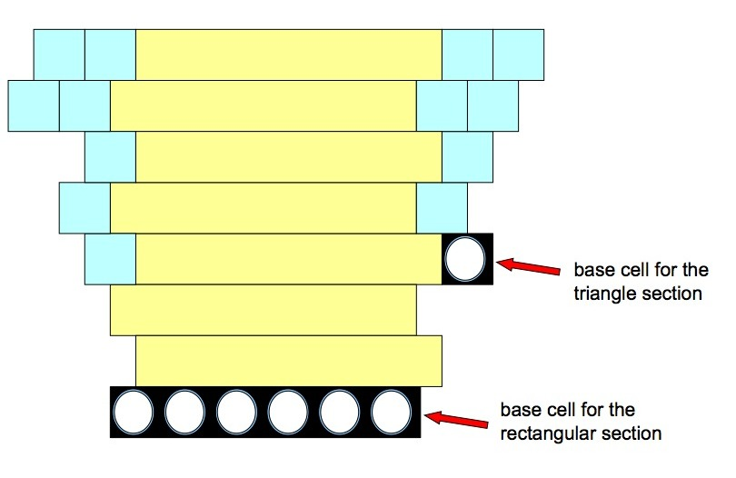
This cell is replicated 199 times to build a total number of 200 layers forming the calorimeter module (see left panel in Fig. 5).
Each plane is alternatively shifted of 0.675 mm in order to reproduce the real fiber configuration (Fig. 6).
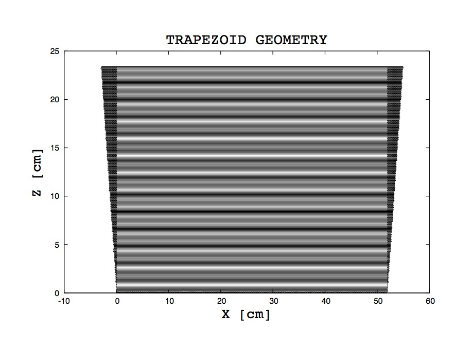
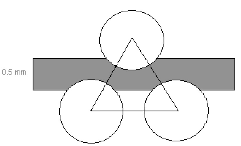
In order to implement the whole barrel calorimeter into FLUKA we extended the rectangular module to the realistic trapezoid shape. This has been achieved by declaration of a new base cell consisting of a scintillating fiber and glue cylinder both inserted into a small block of lead. The length of the cell is equal to the length of the module (4.3 m) and its cross section corresponds to the square of 1.2 mm, where the fiber diameter is equal to 1 mm and width of the glue cylinder equals to 0.1 mm. Then this new base cell was replicated about 4000 times to build two triangular sections on the left and right side of the module (see Fig. 7). A lattice transformation from the 4000 replica to the base cell provides the needed translation.
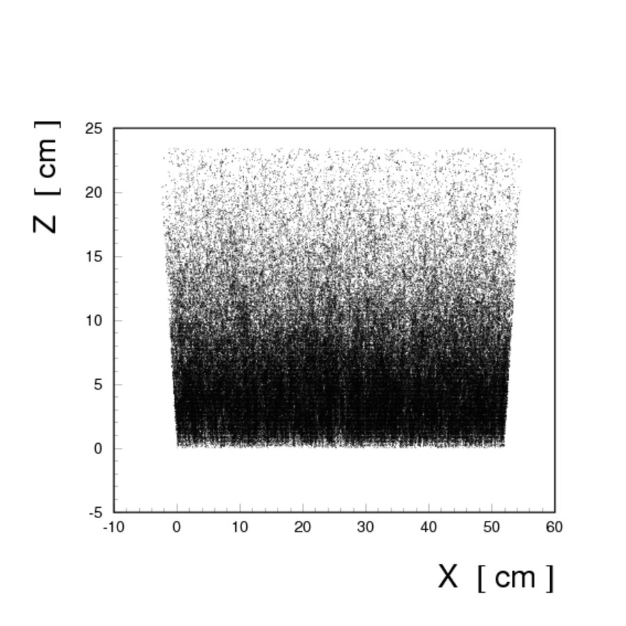
A complete visualisation of the new trapezoid geometry [Visualization is based on the FLUKA sources and prepared using a FLAIR (FLUKA advanced visualization geometry tool [4])] is shown in Fig. 5, whereas the scatter-plot of single energy deposits from homogenously distribution photons hittting the module are shown in Fig. 8: a trapezoid structure which was built with realistic energy deposits from the scintillating fibers can be easily recognized.
As a next step, it would be natural to replicate 23 times the defined geometry for one module and to build a full barrel. This task was unfortunately impossible to realise with the using by us version of FLUKA [FLUKA 2008.3 for GNU linux operating system] because this version doesn't permit to replicate the region which had been replicated before [5]. It is due to the fact that the lattice replication on the second and higher levels is not implemented yet. This is the reason why geometry was built in another, unfortunatelly much more complicated way.
Giuseppe Battistoni; INFN, Milano
Last updated: 26th of October, 2010 |


© FLUKA Team 2000–2025