|
|
|
|
Quick launch:
Last version:
News:
--
Fluka Release
|
[ 1 ] [ 2 ] [ 3 ] [ 4 ] [ 5 ] [ 6 ] [ 7 ] [ 8 ] [ 9 ] [ 10 ] [ back ]
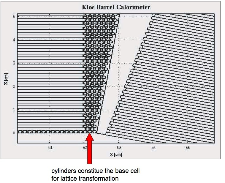
The barrel was first defined as 24 empty volumes (containers). In one of these volumes we implemented the base cell which describes
one layer of lead, fibers and glue. This cell was replicated 199 times in this volume, to build a rectangular section part of the main
trapezoid module (Fig. 9, left), the same idea
was used to build a single module with rectangular shape, and this base cell
was replicated 200 times in each of the remaining 23 modules (see Fig. 10).
A program code with lattice transformation that performs a rotation and 200 translations for each
module can be examined in appendix A. The remaining two triangle areas in the
first module are filled with the real structure of lead, fibers and glue
cylinder. These two regions were then replicated at the corresponding
positions in the remaining modules, through a single
rotation for each module (Fig. 9, left)
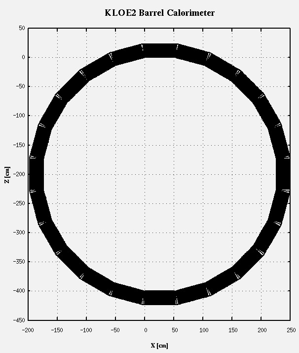
Fig. 10 shows a visualisation of the whole barrel calorimeter geometry. Using this geometry we are able to study in detail energy deposits also at the edges of the modules.
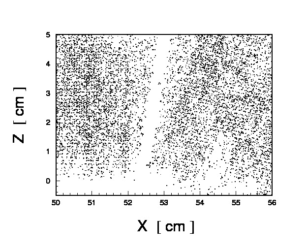
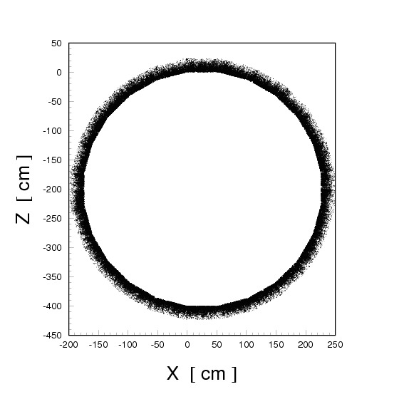
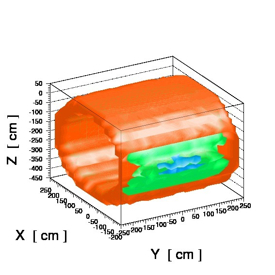
Finally in Fig. 11, as an example of the proper implementation of the geometry we show energy deposits in scintillating fibers in the whole barrel calorimeter.
Giuseppe Battistoni; INFN, Milano
Last updated: 26th of October, 2010 |


© FLUKA Team 2000–2025