Date: Tue, 22 Oct 2013 14:29:07 -0700
Thank you Alberto, Mario, and Keith.
I took your advice and did not use either PE or HDC (High Density
Concete) for our 100 kW electron beam dump (BD) shielidng.
For PE, I took 1E5 Gray as the lower value recommended for a threshold
and we are dealing with dose rates on the order of 1-1E4 Sv/h, depending
on the layer.
As you said, without properly testing HDC samples, we won't know the
composition and the uniformity/homogenity of the mix might not be possible.
I wanted to do away with lead because of the high enutron production
rate (3x as much as steel at 75 MeV e energy). I tried A36 steel (which
is 98% iron) + concrete and that works; however, I ended up using an
inner layer of lead around the Al BD because of 1) ease of cooling an
inner layer of lead than steel (from the Engineer working on the
design), and 2) for better attenuation of the forward-going photons.
This is because of the spatial constrains we need to work with. There
is a wall directly behind the BD and we wanted to reduce the activation
of the wall.
So the final desin is an inner layer of Pb forllowed by layers of normal
concrete and steel. I have found that layering steel and concrete is
more efficient at attenuating photons & neutrons than having an inner
piece of steel followed by concrete. The upstream part of the shielidng
is still under study since the beamline components and positions need to
be defined.
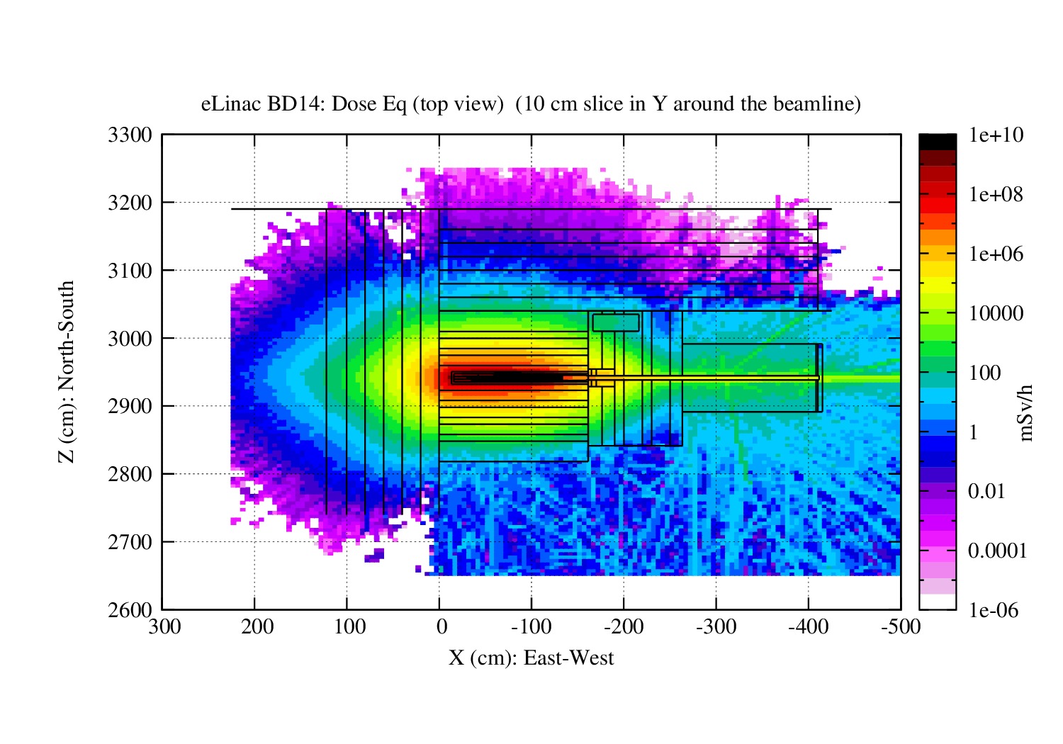
I am attaching a top view of the total dose rate distribution for this
design. The BD sits on the electron hall. In the image you see the BD
tucked in the corner of North and West wall.
Best wishes,
Mina
On 13-09-27 01:18 AM, Alberto Fasso' wrote:
> Hi Mina and Mario,
>
> please let me give a little contribution to your discussion.
> In my experience, the best shielding for high energy neutrons is iron,
> followed by a hydrogenated material (plastics - not necessarily
> polyethylene - if
> radiation damage is not an issue, otherwise simple concrete or even
> water if it is technically possible). Via inelastic reactions, iron
> quickly slows down high energy neutrons to energies where scattering
> by hydrogen becomes effective.
> Heavy concrete is not as good, for the reasons explained by Mario (cost,
> non-uniformity, unknown composition) but especially because the two
> moderation
> effects (inelastic reactions and scattering on hydrogen) take place in
> the same material, while separate iron/concrete shields perform the
> slowing
> down in sequence: first the high energy neutrons via inelastic
> reactions, and
> then the resulting low energy neutrons via scattering on hydrogen.
> This is easily checked with FLUKA.
> The widespread, but undeserved, popularity of heavy concrete is due
> mainly to
> its use in pure photon fields without neutrons (i.e. photons of less
> than 7
> MeV, that cannot produce neutrons). In these cases, all that matters are
> average Z and density which are well provided by heavy concrete.
> I also confirm that lead is bad for shielding, for the reasons given
> by Mario,
> but also: for photons because each photon absorption is followed by
> fluorescence, which must be shielded against too; and for neutrons,
> because
> (n,xn) reactions increase the number of neutrons instead of decreasing
> it.
> This latter effect is much less important in iron.
>
> Alberto
>
> On Thu, 26 Sep 2013, Santana, Mario wrote:
>
>> Hi Mina,
>>
>> Just some thoughts?
>>
>> You know that lead is not the best shielding for high energy neutrons.
>> They will bounce through the structure and make it to the other end of
>> your shielding. A light material will reduce the energy of the neutrons
>> very effectively at each collision. Moreover, it has a fairly large
>> photo
>> neutron cross-section. Also lead is toxic, and when exposed to radiation
>> it will become 'mixed waste', so you may want to minimize its use.
>> This is
>> why it is often used close to the source, to absorb most of the
>> electromagnetic cascades, and then concrete is used in the accelerator
>> enclosure to 'take care of the neutrons'.
>>
>> Polyethylene is a good option for neutrons (specially if it is borated),
>> but as you indicate it may degrade (and also catch fire). Also it is
>> less
>> dense than concrete so it does not absorb photons as well as
>> concrete. An
>> advantage over concrete is that its residual activity is mainly
>> short-lived.
>>
>> About heavy concrete, it is a hybrid solution that seems to work
>> successfully when shielding space is scarce, but it is expensive and you
>> have to make sure that your heavy concrete is sufficiently homogeneous.
>> Also some suppliers don't provide the composition, so you may have a
>> hard
>> time to simulate its effects.
>>
>> Mario
>>
>> On 9/26/13 6:21 PM, "Mina Nozar" <nozarm_at_triumf.ca> wrote:
>>
>>> Just wanted to update everyone with my finding on this. Because the
>>> beam energy (75 MeV) is way above the neutron production (gamma, n)
>>> threshold in lead (6.73 MeV), there are lots of neutrons generated in
>>> the lead. These neutrons in turn produce other gammas through (n,
>>> gamma) reactions. So the effectiveness of lead in shielding gammas
>>> stop
>>> at some thickness (for energies higher than the gamma, n threshold).
>>> The way I got around this was to layer the shielding design (Pb + PE +
>>> Pb + PE ...). This design works in attenuating photons and neutrons so
>>> that the total dose rate is below the required limit.
>>>
>>> However, I am wondering about the radiation resistance properties of
>>> Polyethylene. The first (innermost) layer of PE is seeing Dose
>>> rates on
>>> the order of 1E7 mSv/h or 10 kSv/h, so very high. Looking through
>>> literature, I am seeing Total dose limits of 1E6 Gy (or Sv) - from CERN
>>> 98-01. This gives 100 hours of operation before PE is damaged.
>>>
>>> So I am thinking the Pb/PE layering is not a viable option. Does anyone
>>> know of PE being used in high radiation fields? Does anyone have
>>> experience in this area?
>>>
>>> Another option I have investigated is to use high density concrete
>>> which
>>> seems to do the trick. So we might go with that. I just want to make
>>> sure I am not missing something before writing off the Pb/PE layering
>>> option.
>>>
>>> Any help/advice is appreciated.
>>> Best wishes,
>>> Mina
>>>
>>> On 13-07-19 06:19 PM, Mina Nozar wrote:
>>>> Hello everyone,
>>>>
>>>> We are working on optimizing the shielding for a 100 kW (75 MeV,
>>>> 1.3 mA)
>>>> electron beam dump. BD is basically a chunk of Al with a slanted
>>>> plane
>>>> in the middle to distribute the incident beam (square in shape 4x4
>>>> cm).
>>>> The BD is surrounded with lead and concrete, lead and polyethylene
>>>> (PE),
>>>> or lead and borated PE(BPE) depending on the study. The BD is 111 cm
>>>> long, 20 cm wide, and 12.5 cm high.
>>>>
>>>> In order to compare thickness of PE, BPE, or concrete required in
>>>> shielding neutrons and finding the minimum thickness of lead
>>>> required to
>>>> bring down the dose rates from photons to meet different limits, I
>>>> have
>>>> been looking at dose rate distributions from neutrons and photons
>>>> separately.
>>>>
>>>> I have set the production and transport thresholds for e+/e- to 100
>>>> keV
>>>> and 10 keV for photons.
>>>>
>>>> I originally thought if I extracted TVL from the attenuation of
>>>> photons
>>>> in lead and neutrons in concrete (PE/BPE), I could find the required
>>>> thickness of each material to reduce the dose rates down to the
>>>> limits.
>>>> However, I have observed a 'build-up' behaviour of photons in lead
>>>> that
>>>> I don't understand (and which is affecting my conclusions). I would
>>>> like to find out whether this is a by product of geometry effects,
>>>> thresholds set, etc. or if this is a real build-up effect I am
>>>> observing, suggesting that past some thickness, the effectiveness of
>>>> lead to shield photons goes down.
>>>>
>>>> I am attaching plan and side views of the geometry around the BD
>>>> and two
>>>> figures showing 1-D distributions of the dose rates (from neutrons,
>>>> photons, and total), as a function of width and height of the BD. The
>>>> slices I have made are 10 cm wide around the beam line and center
>>>> of the
>>>> beam dump. The arrows point to the areas showing the 'build up'
>>>> feature which continues through the lead/concrete boundary.
>>>>
>>>> I am showing results of the lead and concrete study only but I observe
>>>> the same behaviour for lead and PE.
>>>>
>>>> Thank you very much for any insight you might have on this. I
>>>>
>>>> Best wishes,
>>>> Mina
>>>
>>
>>
>
(image/jpeg attachment: eLinBD14_DoseEq_BD_All_TopView.jpg)